
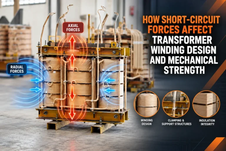
A transformer must withstand more than normal operating voltage and load current. During a short circuit, the sudden increase in current creates intense electromagnetic forces that act on the windings and supporting structures. Understanding transformer short-circuit forces is essential for designing equipment that can withstand electrical faults without permanent mechanical damage.
For industrial facilities, substations, and utility networks, the mechanical strength of a transformer is an important part of long-term reliability. Selecting a capable transformer manufacturer in India means considering not only rated capacity and voltage but also the transformer’s ability to withstand the mechanical stresses associated with fault conditions.
Understanding how short-circuit forces affect transformer winding design is essential for ensuring mechanical strength, protecting insulation, and improving transformer reliability during electrical faults.
What Are Transformer Short-Circuit Forces?
When a short circuit occurs in a connected electrical system, the current can rise to several times the transformer’s rated current, depending on system impedance and fault conditions. The magnetic fields produced by these high currents interact with one another, generating electromagnetic forces within the windings.
These forces depend on factors such as fault-current magnitude, winding geometry, conductor arrangement, and the transformer’s electrical design.
Two major types of forces are involved:
- Radial forces: Act inward or outward on the winding structure, potentially causing hoop stress, conductor deformation, or buckling.
- Axial forces: Act along the winding axis and can compress or displace winding sections, spacers, and supporting components.
The actual force distribution depends on winding configuration, current direction, and magnetic-field geometry.
How Short-Circuit Forces Affect Transformer Windings
1. Radial Forces and Winding Deformation
Radial electromagnetic forces can subject windings to significant mechanical stress. Depending on the winding arrangement, these forces may cause inner windings to experience compressive stress or outer windings to experience tensile stress.
If the winding lacks sufficient mechanical support, the conductors may deform. Such deformation can reduce clearances, damage insulation, and compromise the transformer’s ability to withstand future electrical stresses.
A robust design considers conductor dimensions, winding geometry, clamping arrangements, and the mechanical strength of supporting structures.
2. Axial Forces and Winding Displacement
Axial forces can become particularly significant when ampere-turns are not perfectly balanced or when leakage flux creates concentrated forces near winding ends.
Excessive axial stress may cause winding displacement, spacer damage, or loss of compression. Even small changes in winding position can affect insulation clearances and mechanical stability.
For this reason, winding alignment, end supports, clamping pressure, and manufacturing tolerances are important considerations during transformer assembly.
3. Insulation Damage Following Mechanical Stress
Transformer insulation is designed to withstand specified electrical and thermal stresses. However, mechanical movement during a fault can damage insulation barriers or reduce clearances between conductive components.
This may create conditions for partial discharge or insulation breakdown under subsequent operating stresses. Short-circuit withstand capability therefore depends on both the electrical insulation system and the mechanical integrity of the winding assembly.
Key Design Factors That Improve Short-Circuit Withstand Capability
Winding Geometry and Conductor Selection
Winding dimensions, conductor type, and conductor arrangement influence current distribution, leakage flux, and mechanical stress. The design must balance electrical performance, thermal behaviour, and mechanical strength.
Clamping and Support Structures
Properly engineered clamping systems help maintain winding compression and prevent displacement during high-current faults. Insulation cylinders, spacers, end rings, and structural supports must be suitable for the expected forces and operating conditions.
Short-Circuit Current and System Impedance
The prospective fault current depends on the upstream network, transformer impedance, and the location of the fault. Lower impedance can result in higher fault current for a given system voltage and network configuration.
Transformer design must account for the specified electrical system conditions rather than considering rated current alone.
Manufacturing Quality and Verification
Correct assembly, dimensional control, winding alignment, insulation placement, and clamping are essential to achieving the intended mechanical performance. Applicable design calculations and testing requirements should be considered in accordance with relevant standards and the specified service conditions.
This is one reason industrial buyers should evaluate the technical capabilities and quality processes of a transformer manufacturing company in India, rather than comparing suppliers only by rating or purchase price.
Why Short-Circuit Strength Matters When Selecting a Transformer Manufacturer
For industrial plants, infrastructure projects, and utility applications, a transformer fault can lead to equipment damage, downtime, repair costs, and operational disruption.
When evaluating power transformer manufacturers India, buyers should review the proposed rating, voltage class, impedance, applicable short-circuit withstand requirements, installation conditions, and supporting technical documentation.
Businesses searching for transformer manufacturers in Pune should also assess whether the manufacturer can supply equipment aligned with the project’s technical specifications and applicable standards.
Conclusion
Transformer short-circuit withstand capability depends on coordinated electrical design, winding geometry, mechanical support, insulation integrity, and manufacturing quality. Strong winding construction helps the transformer withstand the electromagnetic forces generated during fault conditions.
MSC Transformers focuses on transformer solutions for industrial and power-distribution applications. Project-specific requirements should be reviewed with the manufacturer to determine the appropriate design and technical specifications.
Planning a transformer installation or replacement? Contact MSC Transformers to discuss your application, voltage requirements, capacity, and technical specifications.
Frequently Asked Questions
They are electromagnetic forces created when high fault currents interact with the magnetic fields surrounding transformer windings.
Radial forces act toward or away from the winding centre, while axial forces act along the winding axis. Both can affect winding stability.
Yes. The mechanical stress during a fault depends on current magnitude and duration, among other factors. A brief fault can still create significant forces.
It is addressed through appropriate winding geometry, conductor selection, mechanical supports, clamping systems, insulation design, and verification against applicable requirements.
Ask about the rated capacity and voltage, impedance, specified short-circuit withstand capability, applicable standards, and technical documentation relevant to the application.